|
Hefei LuJiang ChengChi Industrial Furnace Factory
|
Automatic hydraulic water cooling test quenching tank Quenching oil tank quenching water tank quenching water tank
| Price: | 10.0 USD |
| Payment Terms: | WU,Paypal,Money Gram |
| Place of Origin: | Anhui, China (Mainland) |
|
|
|
| Add to My Favorites | |
| HiSupplier Escrow |
Product Detail
The automatic hydraulic water cooling test quenching tank is a quenching tool specially developed according to the needs of the laboratory. It is wide
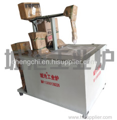
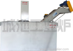
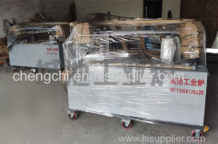
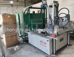
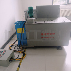
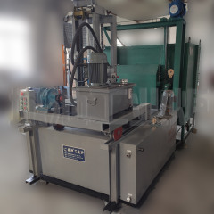
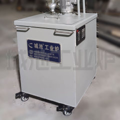
Automatic hydraulic water cooling test quenching tank
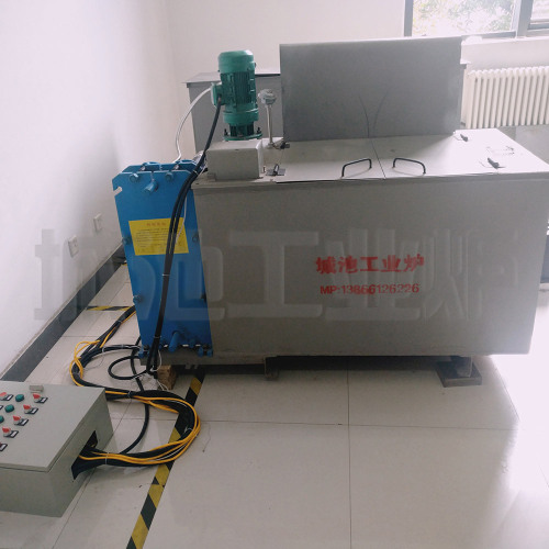
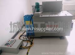
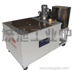
The automatic hydraulic water cooling test quenching tank is a quenching tool specially developed according to the needs of the laboratory. It is widely used in research institutes, universities and other units for various experimental mechanical parts, gears and other quenching oils with constant temperature requirements. Quenching treatment in quenching aqueous solution, automatic hydraulic water cooling test quenching tank can better control oil temperature, with automatic cutting quenching platform, workpiece falling into oil pool is fast, 2-3 times faster than general driving, greatly shortened The time during which the workpiece stays in the air is consistent with quenching and cooling. The quenching tank is provided with a medium stirring device. The medium temperature is uniform and the flow is in the effective quenching zone. The deformation of the workpiece is small, the quenching hardness is uniform, and the workpiece can be closed automatically when it descends to the top. The quenching oil tank cover solves the hidden danger of quenching oil fire and greatly improves the safety standard of fire protection. When a large amount of open flame is generated inside the oil pool, a nitrogen gas (carbon dioxide) pipe is sprayed around the upper part of the oil pool, which can be turned on in time to extinguish the open flame.
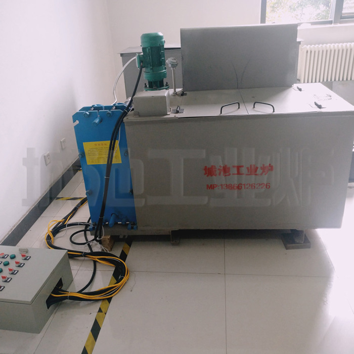 Automatic hydraulic water cooling test quenching tank
In order to facilitate transportation, the quenching tank of this experiment is designed in a rectangular shape and placed directly on the ground. It is easy to move through the bottom pulley and can be positioned by pressing the brake. There is a stirring motor on the side to form a mutual convection stirring mode, so that the quenching oil in the quenching tank has a uniform temperature above and below, and a horizontal lifting table is arranged in the middle for placing the processed parts, and is used with the control cabinet through the hydraulic station system piping. To control the upper and lower sides of the quenching table, when the workpiece is placed on the table and the table starts to descend, the quenching oil tank door automatically falls, and the combustion of the open flame can be controlled smoothly and timely. The oil temperature is controlled by the heating tube to the quenching required temperature, high temperature. Oil pressure and medium (water, wind, gas) coolers are exchanged to complete the oil temperature drop, and our heat exchange coolers are also available. There is a pipeline around the upper part of the quenching oil tank, the side is covered with dense holes for spraying, and the other end is connected to the outside of the quenching tank (can be connected with nitrogen or carbon dioxide pipeline) to control the use of open flames, if there is an emergency, such as In the event of power failure or mechanical failure, manual blanking can be used. The quenching tank immediately opens the clutch device to allow the workpiece to fall into the groove, and the workpiece will not stay at the quenching table at any time.

The automatic hydraulic water cooling test quenching tank adopts automatic control system, which has small floor space, simple and convenient operation, less waste gas, fireproof and standby fire extinguishing system, and complete functions (the quenching oil tank can also be used as quenching tank and quenching tank). Function customization, close to the user's needs, advanced and reliable design, even in the case of power outages or mechanical failures, can be manually and quickly cut off, greatly improving the fire safety of the equipment, well received by the majority of research institutes, colleges and universities. You are welcome to call us for advice.
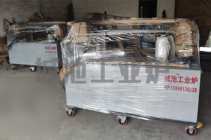
Table: Specification and Size Table of Quenching Tank
| Material frame size(mm) Length×Width×Height | Installed capacity(L) | Power (kW) | Mixing power supply (w) | ||
| MQT/MC-36 | 300×400×500 | 200×150×80 | 36 | 1 | 300 |
| MQT/MC-72 | 400×500×600 | 250×150×100 | 80 | 2 | 300 |
| SQT/SC-12 | 500×600×600 | 300×200×100 | 120 | 3 | 550 |
| SQT/SC-20 | 800×600×600 | 350×200×100 | 200 | 5 | 550 |
| SQT/SC-32 | 1000×800×600 | 400×250×100 | 320 | 8 | 750 |
| SQT/SC-48 | 1500×800×600 | 450×250×150 | 480 | 12 | 750 |
| SQT/SC-72 | 1800×1000×600 | 500×300×150 | 720 | 18 | 1500 |
| SQT/SC-100 | 2000×1000×700 | 500×300×200 | 1000 | 27 | 1500 |

